Even a careful designer can fall into one of these common traps when calculating design elements within residential timber structures.
Any building industry practitioner designing a structure understands that individual, or groups of members are designed by following a series of logical decision-making steps:
Determination of the loads the structure is likely to experience over its lifetime. This will include permanent loads (typically the structure itself and fixed objects) and imposed loads such as floor live loads due to people and furniture, and of course the effects of wind loads on the overall structure.
Calculation of the element size and type via engineers’ calculations, span tables or structural software – this software is often supplied by distributors of EWP because their product usually has individual structural properties. In general, the design of the structure will be based upon strength and serviceability (deflection) criteria defined within relevant standards referenced in the NCC.
Combination of those elements into a complete structure expressed via drawings and specifications to facilitate construction.
That said, there are still traps to be found. Here are a few areas that create challenges when designers are calculating the design elements within residential timber structures.
TRAP #1 – ACCUMULATED DEFLECTIONS
A designer can use the tools at their disposal to correctly design all the individual elements to have expected deflections less than the maximum required by a relevant standard. It is only when they are added to a ‘system’ where elements are supported by each other, that unforeseen outcomes may arise.
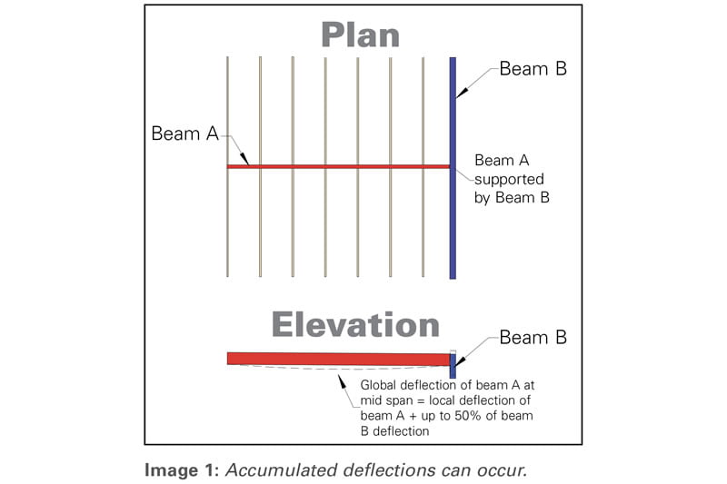
For example, consider intermediate floor bearer Beam A, which in turn has one end supported by Beam B. Beam B is also a load bearing beam in its own right, supporting wall and roof loads (See Image 1, above).
In isolation, but following the deflection (serviceability) limits of AS 1720.3:2016 for bearers, both beam A and beam B were designed to the maximum permanent deflection of 12mm.
This is where the system effects begin to operate. Because one end of Beam A is supported at the midspan of Beam B, this end is now shifted lower by the deflection of Beam B. Therefore, the global deflection of Beam A is 12mm at its midspan + 12/2mm from Beam B, which gives a total of 18mm.
If Beam B was also supported by elements down the load path that allow some deflection, then it follows that there could be further deflection accumulated at the midspan of Beam A.
In practice, very few bearers are designed to their maximum serviceability limits, and therefore the above is an extreme example, however the concept of deflection accumulation must be considered by designers. If Beam A was a beam over an operable wall that required tight tolerance to prevent the door jamming, then the deflection of a beam lower down on the load path may only manifest as a critical issue at the top of the structure.
Good software packages will help you to design with these accumulations in mind. For example, the free SmartFrame software offered by Tilling allows the user to input design data such that the loads from one element can be added to another to create a load path, thus this cumulative deflection can be easily modelled.
TRAP #2 – VARIATION OF JOIST DIRECTION
In a very competitive environment, especially in the project housing market, a designer of a floor system is encouraged to look for the most economical joist/bearer layout as possible. Often this action results in the need to change joist directions over different parts of the floor system to best match the span capabilities of the joists. Joist direction changes and a mixture of span types can be a powerful tool for the designer but, unless managed carefully, may also lead to unforeseen issues.
Consider a change in joist direction at a wall brought about by the geometric shape of the lower floor in Image 2 (below).
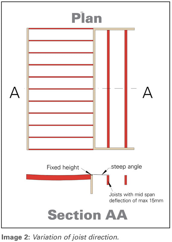
This example is potentially a trap that designers need to manage carefully. The joists shown horizontal are supported at the wall and are thus fixed in height at that point. The first long span joist running parallel to the internal wall theoretically may have up to 15mm permanent deflection at midspan – along the line marked between A and A (Line AA).
From the fixed height at the wall, the floor level drops the 15mm in the distance of a joist spacing (usually 450-600mm). I have personally experienced this phenomenon as I walked along a real life Line AA and suddenly felt catapulted forward when stepping into this area where the joists run in the other direction.
While it is unlikely that a real-life example is going to be quite as severe as the 15mm scenario described above, the example is used to demonstrate what may happen if designers are not aware of this potential design issue. Notwithstanding that this is an extreme scenario, experience shows that even a small variation in height over a short distance within a floor is discernible by occupants of the dwelling.
TRAP #3 – DEFLECTION OF RAFTERS/JOISTS ADJACENT TO A PARALLEL WALL
While this trap is similar to the previous example, it often manifests itself more as a visual issue. When someone in the building walks upstairs, at the point where their eyes are at the level of the ceiling (under upper floor joists or rafters), they can look along the ceiling plane to a straight feature behind, thus noticing the curvature of the deflected element.
Consider the common example of long rafters with a fitted ceiling, adjacent to a raked wall (Image 3, below).
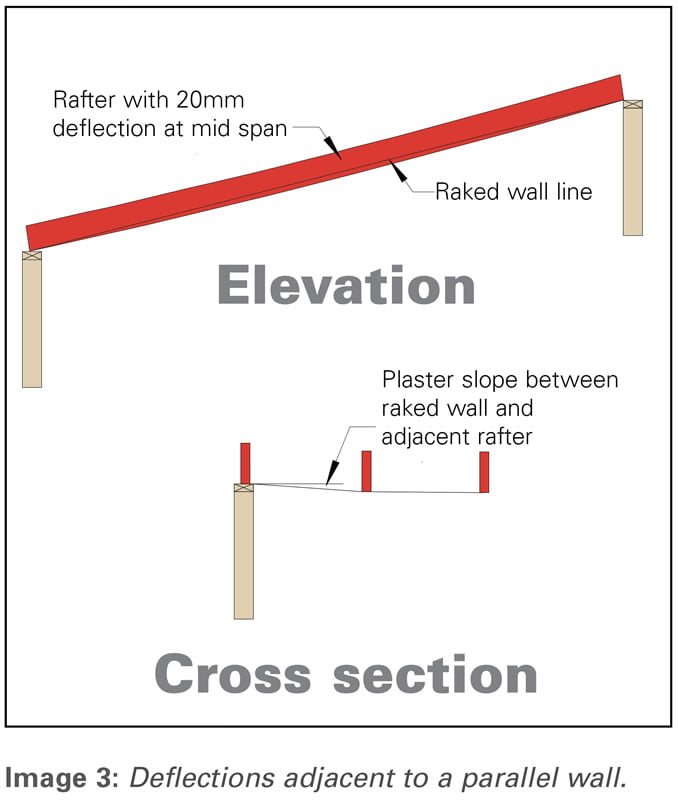
A long span rafter with ceiling may have a permanent deflection at mid span of up to 20mm. The adjacent wall that is built on the rake will have a consistent rise (straight line), and at the ends of the rafter will be at the same level. At midspan however, the parallel rafter, will deflect down 20mm below the wall line.
If there is a wide spacing of rafters, this variation may not be terribly evident, but if the rafter spacing is down to 600mm, then the slope of the ceiling from the wall to the first rafter becomes more evident.
If there is a stair to an upper level and a person can look along the ceiling line against a straight edge, the deflection becomes immediately evident, and oftentimes the homeowner will raise a concern.
For most people, the residential house is their largest single investment in their life, and they understandably take the building of their new home very seriously. In my experience, it is very hard to convince a new homeowner that some visible deflections are to be expected.
Experience shows that if a building designer is cognisant that they not only have to correctly design individual elements, but they also consider the combination of those elements, and relative deflections of elements adjacent to a fixed object, many of these traps described above can be avoided, and thus deliver happy homeowners.
For more information on this topic, contact Craig Kay and the Tilling engineers via email at techsupport@tilling.com.au


