Solving wind bracing isn’t a one-step process and ensuring the adequacy of every link is vital. By Afzal Laphir, Principal Engineer, Meyer Timber Pty Ltd.
The saying ‘the chain is only as strong as its weakest link’ is commonly used as a metaphor for the strength of any system that is made up of multiple parts. Be it a football team, the drivetrain of a car or even a combination of structural connections, the same saying holds true. It is no different when looking at the lateral stability of a home.
Wall bracing design fundamentally involves the determination of horizontal wind (racking) forces on the building, in two perpendicular directions, and then providing sufficient bracing units to resist these racking forces. That sounds simple enough on paper and, once done, the job is completed to many wall designers.
However, in reality, the provision of bracing units is only one link of the chain that ensures racking forces are effectively transferred to the ground. This transfer takes place through a load path that is formed by a complex interaction between the walls, ceiling/roof structure and floor structure, translating to a simple chain with several links, as illustrated in Fig 1 (below).

Let us dive deep into these links and explore the roles each of them plays in an effective bracing system.
Structural ceiling or floor diaphragm
Ceilings and floor structures form large horizontal diaphragms that play an important role in the structural integrity of a building. For the diaphragms to work properly, the ceiling sheet must have direct/positive fixing to the roof structure, i.e. the truss bottom chords or ceiling joists. Ceiling battens, if used, must be fixed positively to the truss bottom chords. Ceilings that are suspended or fixed via clipped-on metal furring channels do not provide this connection.
In addition to connections, the depth and span of the ceiling diaphragm are two other critical factors that determine its capacity. A deeper diaphragm is required to distribute wind loads over a larger distance.
In low wind areas (N1 or N2), AS 1684 allows ceiling diaphragms to span 9000mm without any restriction on depth (clause 8.3.6.7) and floor diaphragms to span 14,000mm for a minimum depth of 4800mm (clause 8.3.5.9). Table 1 (below) summarises the AS 1684 requirement, where the span of diaphragm is taken as the spacing between bracing walls.

Clause 1.4.8 of AS 1684 allows an alternative system to be specified if the above requirements are not met, provided it is designed and approved in accordance with engineering principles. These systems may include one of either a wind beam, wind truss, steel cross bracing or a plywood bracing system.
Connections to top of bracing walls
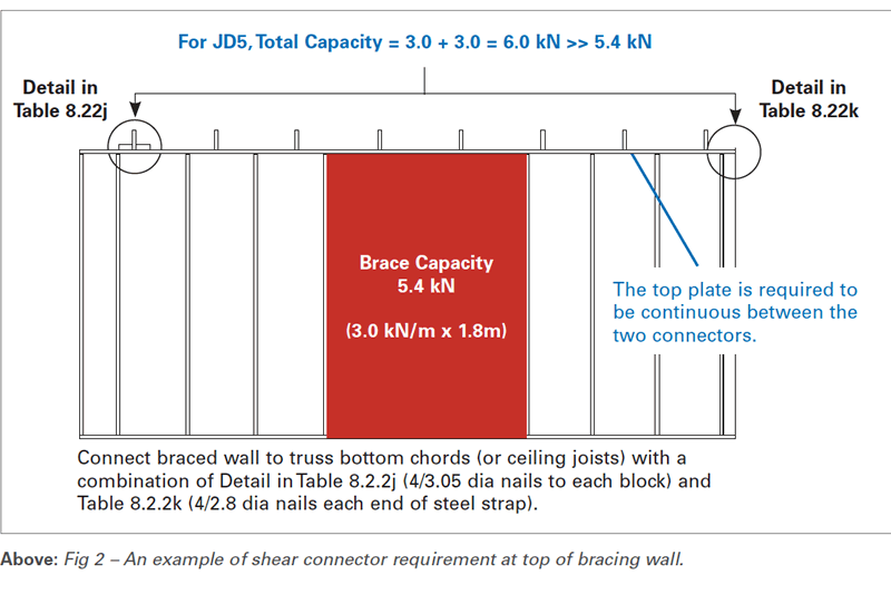
Clause 8.3.6.9 in AS 1684 states that “All internal bracing walls shall be fixed to the floor of lower storey bracing walls, the ceiling or roof frame and/or the external wall frame, with structural connections of equivalent shear capacity to the bracing capacity of that particular bracing wall.”
Typical details and shear capacities are specified in Table 8.22 of AS 1684. A combination of these shear connectors may be used to satisfy a single bracing unit. If required, they can be located outside the width of the bracing unit, but in the same wall as long as the top plate is continuous between the shear connectors. Refer Fig 2 (main image) for an example.
A few alternate products to those given in Table 8.22 are available, for example the SDPW Deflector Screw from Simpson Strong-Tie, which can function both as a shear connector as well as a connector that provides lateral stability to non-loadbearing walls.
Connections to bottom of bracing walls
As stated in clause 8.3.6.10 of AS 1684, the bottom plate of timber-framed bracing walls shall be fixed at the ends of the bracing panel and, if required, intermediately to the floor frame or concrete slab with connections determined from Table 8.18. For bracing systems with racking capacity up to 3.4 kN/m, specific tie-down connectors are not required, meaning nominal fixing of the bottom plate to floor frame or slab as per Table 9.4 is sufficient.
For racking capacities greater than 3.4 kN/m, Table 8.18 AS 1684 nominates specific fixing comprising of M12 rods or a 13 kN connector at each end of bracing units as well as an intermediate 13 kN connector at 1200mm centres. Several tie-down connector options are given in Table 8.24 to achieve this 13 kN requirement, but the most common connector used in practice is the M12x150 concrete screwbolt or anchor screw.
Even distribution of bracing walls
Clause 8.3.6.6 in AS 1684 requires bracing units to be “approximately evenly distributed and provided in both directions.” It also states that “bracing shall initially be placed in external walls, and where possible, at the corners of the building.” This is easier said than done given the complex nature of modern houses.
One way to achieve this is by drawing a grid pattern of bracing lines, in the two perpendicular directions, that coincide as much as possible with wall bracing units. Then, locate these units evenly throughout the building and as close as practical to corners and external walls.
Where bracing units cannot be placed in external walls because of openings, AS 1684 allows wall frames to be designed for portal action (refer clause 8.3.6.7). A number of engineered timber solutions are available for this application such as meyBRACE from Meyer Timber.
Having discussed the individual links of residential lateral stability chain it is important for a wall designer to identify the weaker links and pay closer attention to them.
This might require validating some of the common assumptions made in wall bracing design. For example, a knowledge of the fixing method of ceiling will enable the designer to determine its effectiveness as a diaphragm and specify an alternative at the time of the design.
It might also be useful to prepare a sheet with a list of common connections to bring this to front of mind for the installer.
The overall system for lateral stability has a number of links and from above you can see that the original quote holds true – the system as a whole is only as strong as the weakest link. There is no point having Ronaldo on your team if you have a third-string goalie.
For more information on this topic, contact Afzal Laphir via email at AfzalL@meyertimber.com.au


