Taking more care when cutting access holes can save a lot of time and worry. By Afzal Laphir, Principal Engineer, Meyer Timber
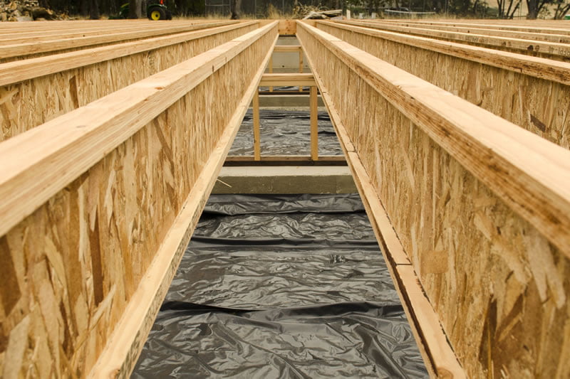
Prior to the mid-1980s, floor systems were generally made out of solid joists which gave limited opportunities to put penetrations through. So, dropped ceilings and bulkheads were the accepted practice to accommodate services until I-joists and open webbed floor systems came along.
Floor trusses were a godsend to builders as service pipes and ducts were able to be easily navigated within the floor depth. I-joists had their own advantages at a better price point, but there were limitations where the installer could cut the penetrations out.
However, the recent developments in the I-joist offer and the availability of new products have given I-joist users greater flexibility and fewer headaches on site. Running services through I-joist floor systems is easier to achieve now with a little input from the builder at the design and installation stages.
As a starting point, it is important to understand the rules and ‘no-go’ zones for service holes to ensure compliance and getting it right is critical for the structural integrity of the I-joist.
STANDARD RULES
As holes directly impact on the shear capacity of the I-joist, their size and location are dictated by the shear force along the span. For a single-span floor joist, carrying uniformly distributed loads, the shear force moves from a maximum value at the support to zero at mid-span and therefore it is prudent to locate larger holes as close to mid-span as possible.
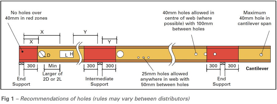
As a basic rule, holes with diameters larger than 40mm are not permitted within a distance of 300mm from the face of a support, sometimes called the no-go zone, shown in red in Fig 1, below.
This rule can become more stringent as the span, loading or the size of hole gets larger. For example, when a 300×45 (MJ300 45) joist at 600mm spacing supporting standard domestic loads is spanning 3.5m (single-span), a 200x300mm rectangular hole is allowed at the minimum distance of 300mm.
However, at its maximum span of 4.6m, the same hole must be located at least 1000mm away from a support. It is therefore important, prior to installation, to understand the recommended hole locations provided by the reputable I-joist distributors. Alternatively, seek advice from their design teams.
Refer to Fig 1 for an illustration of recommended locations, size and spacing of holes (X and Y are distances obtained from separate tables, not included here). Although these rules appear similar, they may change slightly between distributors and the correct product technical literature must be used.
For a given span, the shear force at an intermediate support of a continuous two-span joist is higher than that at end supports of a single span joist. This difference can be as high as 25%, for equal spans, which necessitates separate requirements for holes close to end and intermediate supports. As a reference, the 200×300 rectangular hole in the above example must be 1300mm away from an intermediate support. On a positive side, the impact of holes close to an end-support of a continuous span joist is much lower than for a single span, allowing the 300mm rule to apply in most scenarios which can be verified using I-joist software supplied by engineered timber distributors, such as designIT.
Not only does the distance from the support matter; the number of holes and distance between them also needs to be considered for I-joists. Typically, no more than three (3) holes above 75mm diameter are allowed in any one span and the distance between holes needs to be at least twice the diameter/length of the bigger hole. Again, this should be checked against the relevant I-joist technical literature.
Lastly, multiple holes that are situated close together can be grouped as a single large hole for the sake of checking design suitability.
HOW TO GET IT RIGHT
Despite clear information on dos and don’ts on holes, we continue to experience issues on site as plumbers/electricians go about their task of finding the shortest route for the pipe/duct. The recommended hole locations are sometimes ignored and hammers used to smash holes through the webs. Such errors and damage to joists can be costly to repair, and the degree of difficulty gets worse if service pipes are already in place.
Each trade works independently, and it gets harder to meet the requirements as construction progresses. Often the air conditioning installer, who has to cut the largest penetration, is the last to do so and must work around what has been done before. Better co-ordination between the builder and his trades will go a long way in mitigating these issues. Decisions can be collectively made – early in the process – on the optimum pathway for the service pipes and ducts, ensuring compliance with I-joist distributors’ recommendations.
That said, the best outcome can be achieved only if consideration is given to service installation at the time of design, not just confined to plumbing around wet-areas and electrical layout, but also ducting for air-conditioning, heating and exhaust fans.
If layouts for such services are available, I-joist floor systems can be detailed with holes, sized and located to suit, and even pre-cut on CNC machinery by the distributor if required. The designers can also look at consolidating the services to minimise the number of holes and thus enable easy installation on-site, saving the builder time and money.
HOLE SUPPORT BRACKET
A recent addition to the I-joist offer is the Simpson Strong-Tie hole support (IHS) bracket (see Fig 2, below), which is designed to strengthen I-joists when holes are required to be cut in locations outside standard recommendations.
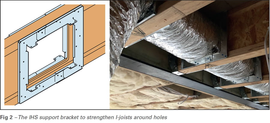
The IHS bracket allows holes to be located as close as 50mm from the face of a support and can be installed even when services are already in-situ, giving significant flexibility to the builder.
Holes through I-joists are easy to accommodate and quick and simple to make but there are limitations on what is allowed. It would be a major benefit for the builder or site supervisor to spend a bit of time once the framing was complete to discuss service runs with their subcontractors and highlight any issues that may arise in terms of hole placement. Or even better still, if this discussion happens at the design stage to make life easier on site. And all trades should be aware of the basic limitations on hole sizes, locations and spacing noted above that are similar for all I-joist products.
Doing this could save expensive repairs and time delays on the job, which is what every builder aims for. And that’s the truth, the hole truth and nothing but the truth.
For more information on this topic, contact Afzal Laphir via email at AfzalL@meyertimber.com.au


