EWP Design Software is no substitute for a fundamental understanding of construction. By Craig Kay, national product engineer, Tilling
SmartFrame software was introduced to the building industry profession in 1997 to equip building designers with the tools to design a new timber I-joist, which has different design methodology to conventional solid timber. For experienced building designers and estimators who had honed their craft over many years, the software not only allowed them to design I-joist but also to refine their designs for conventional timber sections. For the first time, they could input actual spans including uneven continuous spans rather than looking up span tables.
This first generation of software users transitioned from span tables and already had a good understanding of building principles.
Span tables and other deemed to satisfy solutions in AS 1684, by necessity, had a limited range of spans and assumed that continuous spans had lengths within 10% of each other. In general, the person using this new tool still possessed sufficient building proficiency to not only model the element being designed correctly but could immediately understand whether the answer produced by the software was within the expected size range.
Two generations on, we experience a vastly different design/estimation landscape, with the typical estimator now more likely to be tech savvy but less skilled in building construction. This is partly mitigated by more powerful and readily available software.
Crushing values for critical beams
The example below is common, especially in Queensland townhouses, where the upper wall is offset back from the lower wall to increase light penetration. The upper wall is supported by a single beam spanning between perpendicular load bearing walls, i.e., a continuous span beam with its internal support bearing onto a 70mm frame, see Figure 1, below.
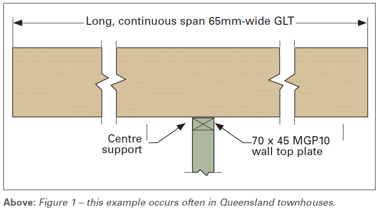
In a tiled roof scenario, and especially with a 65mm-wide GLT/glulam beam capable of fitting within the wall space, the software will emit an error message stating “Support crushing” or similar, depending upon the software. The perpendicular wall plate is 70mm wide, so there is no avenue for adding extra bearing length.
Many SmartFrame software users have attempted to override the error message by simply increasing the beam depth (bigger is better, right?) to the maximum within the software. When they find they cannot, they believe the software to be faulty. This is just one example where some level of building construction skill is so vital.
Cantilevers
Another area where software users not familiar with building construction can inadvertently enter potentially dangerous territory, is in the design of cantilevers. For designers who select member sizes from supplementary span tables to AS 1684, the standard sets limits for cantilever span-to-backspan ratios. For many different elements the ratio can be twice the cantilever length, whereas others can be four times the cantilever length.
Engineering software like SmartFrame allows the user to analyse the forces on cantilevers much more accurately and they can be engineered, if properly detailed, with lower backspan to cantilever ratios than the general rules above. Note the addition of three words, “if properly detailed” in the last sentence.
Static engineering software works on the assumption that the element under consideration is fixed in the vertical direction at each support. The software then analyses the forces in the element and designs the size based upon those forces and somewhere on the results screen or in the computations will indicate the direction of applied forces at the supports for each load case. However, in the scenario shown in Figure 2 (below), the support at the end of the backspan needs to supply a tie-down force to create vertical fixity, and the software output may demonstrate this fact as a negative number for the support reaction.

The span-to-backspan limits set within AS 1684 are designed to safeguard against this scenario by always ensuring that the backspan reaction does not end up as a negative gravity load requiring tie down. This AS 1684 deemed-to-satisfy solution, while preventing uplift issues, on many occasions would give a quite conservative and thus less competitively priced result, or prevent a cantilever being used altogether.
In this age of domestic house layouts and estimates being won or lost over a $50 difference in the quote, the pressure is on designers/estimators to refine the quote for the framing to the nth degree, and thus reduce the volume of material. An estimator/designer who lacks building construction knowledge and experience may not fully comprehend when the software shows negative gravity load at a support. Saving on timber but missing a crucial tie-down in a cantilever is a scenario that can occur in modern software and needs to be carefully managed.
If such a design ends up on site, there is a risk that the carpenter under time pressure is simply going to construct the end connection for gravity loads, and not seek a specific connector capable of providing the required tie down force. In some cases, such as for balcony cantilevers, this connection may even need a 12mm threaded rod connected all the way to the slab.
Call the engineer
People shouldn’t shy away from utilising the powerful design capacity of contemporary EWP software, but in many cases the design outcomes are replacing the role of an engineer. Designers therefore need to be adequately equipped to understand what each software output means, and how that output relates to building design. Each software supplier offers extensive free training and technical support in the use of their software.
A great “safety-first” starting point for new users of EWP software that do not come from the building background, is to seek out those software packages that have been third-party audited to demonstrate conformance with the ABCB Protocol for Structural Software. Conformance with the protocol means essentially two important things:
- Software outputs have been checked by an independent third-party engineer
- Only those input variables used in AS 1684 are available for the user to modify.
The above third-party audited attributes can significantly reduce the risk of costly or unsound designs being produced by the design software packages in our market today.
For more information on this topic, contact Craig Kay and the Tilling engineers via email at techsupport@tilling.com.au


