
Wind beams break some of the ‘rules’ and benefit from close attention. By Afzal Laphir, Principal Engineer, Meyer Timber
In life there are always exceptions. “I before e except after c” is the perfect one for those of you grammar buffs who want to get sufficiently feisty. And when it comes to buildings it’s no different. Normally you install a beam on its edge as that’s when it’s in the stiffest orientation. But there are cases where it needs to work the other way around. Examples are a scaffold plank or wall plate, which are still loaded vertically. Another more obscure but important member in housing is the humble Wind Beam.
Wall frames are required to resist both vertical (gravity) loads from roof truss/rafters and floor joists and horizontal loads due to wind. While the vertical loads are transferred directly to the ground via studs, the load path for horizontal loads is not that straightforward. The studs, in bending, transfer these horizontal loads to the top and bottom wall supports and, through a system of braced walls and diaphragm action provided by ceiling/floor structure, these loads are eventually taken to the ground.
The function of a diaphragm, which is often understated, is to transfer horizontal wind loads from the studs to the braced walls. In the absence of this, as is the case at staircase and entrance voids, a special horizontal member (Wind Beam, see Fig 1, below) is required to fulfil the same function or studs must be designed for twice its height which is neither economical nor within standard design scope.

Depending on the application and the ease of construction, wind beams can be specified as a beam on edge, beam on flat or in the form of multiple wall plates. Each type has its own purpose and a horses for courses approach is necessary to derive its benefits. Let us dive in.
BEAM ON EDGE
Wind beams around floor voids are usually designed on their edge, the same orientation as a standard beam, to ensure they are kept within the confines of the wall thickness (Fig 2, below). However, this differs from standard beams as the horizontal loads subject wind beams to bend sideways (minor-axis) rather than vertically (major-axis). In this application, the beam thickness is more critical than the depth which explains why a single 63mm wind beam works more efficiently than a double 45mm.

The wind beam does not have to act in isolation if the top and bottom plates of the lower and upper-storey walls respectively are constructed with suitable fixings and in single lengths (i.e not joined) along the beam span. These wall plates, with an orientation best suited to resist horizontal loads, offer increased spans to the wind beam configuration as illustrated in Table 1 (below). Given this benefit, a wind beam can also be constructed with multiple wall plates to good effect. A combination of 7/90×45 MGP10 wall plates (315mm total depth) delivers longer spans than a single 300×75 meySPAN13 on its edge. Fixings of these wall plates must be given careful consideration to ensure loads from the walls are adequately transferred.

BEAM ON FLAT
Voids in two-storey buildings may be the most common application of a wind beam, but there is a case for its use in single-storey structures as well. Where diaphragm action is not possible at the ceiling level (eg: dropped ceiling), a separate horizontal bracing system (wind beam or truss) may be required to transfer racking loads to braced walls. Their spans are determined by the spacing of braced walls and as noted in Table 2 (below), standard top plates can fulfil this function if braced walls are available at around 3.0m apart but at larger spacings, a wind beam/truss is required.
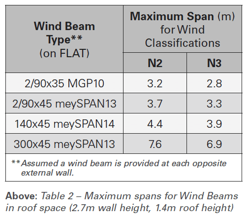
The main difference between a wind beam around voids and in the roof space is its orientation. The former is required to be on its edge as noted above whilst the latter is usually positioned on its flat to maximise its performance (Fig 3).

WINDOWSILLS AND LINTEL TRIMMERS
Windowsills or lintel trimmers also perform a similar task to wind beams in that they transfer horizontal wind loads to the supporting structure, in this case to the jamb studs. Specification for these components can be obtained from Clause 6.3.6.6 or Table 6.3 in AS 1684, noting a lintel trimmer is only required above windows or doors when the lintel is placed directly under the top plate and the distance between the top of the window/door to the top plate exceeds 650mm.
END CONNECTIONS
Like most wall frame components, the efficacy of a wind beam is only as good as its fixings. It is important to fix its ends adequately to ensure the reactions from the beam are transferred to the supporting structure. Unfortunately, standard details for this application are neither available in AS 1684 nor specified in most design software and therefore the designer needs to provide this. You should be able to consult with your local nailplate manufacturer or EWP supplier who can work through this process with you.
Wind beams may be different to what we are accustomed to, and their specification might appear cumbersome, but if you understand and apply the concepts discussed here, there are many combinations to choose from. It is clear from the span tables that void lengths of up to 3.0m can be handled conveniently using standard construction practice without the need for a special wind beam design. In some cases, when the floor void is protected by an adjacent single storey structure like garages or verandahs, a wind beam may not be required at all. However, if you specify a wind beam, make sure you have all the connection documentation included. Otherwise you could end up with issues on site and this means you become the exception to the rule.
For more information on this topic, contact Afzal Laphir via email at AfzalL@meyertimber.com.au


