Cantilevers are increasingly common but require considered design solutions. By George Dolezal, Principal Engineer, Meyer Timber.
Anyone who is involved in the design and detailing of the modern two-storey family home knows that it is not as easy as it used to be. Gone are the days of a nice rectangular box with a hip or gable roof. Now we have to deal with complex roof shapes, brick below and clad above, offset first floor walls with multiple steps in them and, to top it all off, an open-plan ground floor with few internal walls. It’s almost like we need the good old skyhook to hang the first floor off.
What this complexity does is to introduce a lot more instances of cantilevers into a floor system. A cantilever is a structural element that extends horizontally with no support at the end of the beam. In residential house construction a beam which cantilevers will almost always have a ‘backspan’ as shown in Figure 1 (below), which provides stability to the member. Floor bearers and floor joists specified using the AS 1684 span tables require a backspan of at least twice the cantilever to prevent uplift on the support (based on uniformly distributed loads). To further complicate matters there may be more than one backspan, uneven loading or there may be a cantilever at both ends.
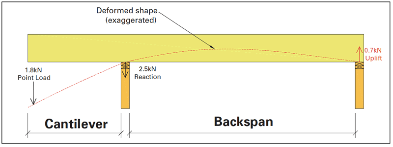
Figure 1
Craig Kay touched on cantilevers in his April 2021 article ‘No silver bullet’ in TTN and I will go a bit deeper into the subject. The important thing for an astute designer to recognise is how the floor is set up and what can be achieved with regards to a cantilever in different scenarios.
What happens if the backspan becomes smaller?
The limits in AS1684 can be reduced but the implications need to be considered. The smaller the backspan the larger the uplift on the end of the beam. These support reaction values are included (with warnings) in common EWP software packages like designIT. If this support is notched into a steel beam then the beam will be providing the uplift resistance. If the member in question is an I-joist butting into a beam, the connection needs consideration as standard face mount I-joist hangers have minimal uplift resistance. You may need to use web stiffeners with a partial depth hanger.
The hidden cantilever
I was recently asked about the design of Beam A shown in Figure 2 (below). A 6m span stair void beam would not work in LVL. But a closer look at this shows the joists are spanning 4.2m and 0.9m if the LVL is a support; OR they are spanning 4.2m with a 0.9m cantilever. This works in the design software, meaning the LVL then becomes an end trimmer to load share across the joists and stiffen them up, solving the issue.
In reality, the relative stiffness between the beam and joist cantilever will determine whether the beam will support the joist or not.

Figure 2: different cantilever scenarios
Brick ledge cantilevers
These are where a 150mm cantilever is included to make the outside of the upper frame line up with brickwork downstairs (see Figure 2). End trimmers are not required with short cantilevers on I-joist floors but may need to be included for tie-down or support of point loads. Short joists running perpendicular to the main span will also be needed where the cantilever is parallel to the run of joists.
Working with corners on a two-sided cantilever
Where you have a cantilever on both perpendicular external walls the corner needs special attention. It is easiest to have a 45° member (like a flat hip) which the joists butt into. But this is more difficult with I-joists and installers have a hard time getting it right. One solution is to design an end trimmer on one side to hold the opposing end trimmer up which makes all the connections easier (See Cantilever Corner in Figure 2). This is something that is best worked out by an engineer, so discuss with your F&T plant or EWP provider. Standard details can be done for more common scenarios.
Windows can help (or hinder)
Where a large cantilever is holding up an external wall with openings in it, the joists under the opening are not carrying any roof load but there will be point loads at the jamb stud locations. It is often easier to design LVL joists at these high load points and then you can remove the roof load in between to aid the design.
Deflections
The cantilever beam is a continuous member, meaning any deflection on the cantilever will help the backspan deflection and vice versa. If there is roof load on the backspan such as a balcony cantilever bearer under an external wall, this should be included as it will help with the stiffness. Also, if you butt into a beam, this will have some deflection in it so the backspan support is not entirely rigid. The effect of this is not easy to quantify but a downwards deflection in a backspan support beam will also reduce the deflection at the end of the cantilever. In the same way, any movement of a joist in a backspan hanger will affect deflections, so the installer must secure hangers with fixings in every available hole.
So, by being able to determine what members are acting as a cantilever and how to manage the connections, you can often simplify layouts for complex house designs. In doing this you must include the right documentation to make sure it will be installed as you have intended.
We may all joke about skyhooks but until they are invented the age-old engineering principle of gravity will continue. Structural cantilevers that are properly detailed and constructed will hang around for the life of the house. And a final constant reminder – if in doubt, check with an engineer before you continue.
For more information on this topic, contact George Dolezal via email at GeorgeD@meyertimber.com.au


